construction line engineering drawing
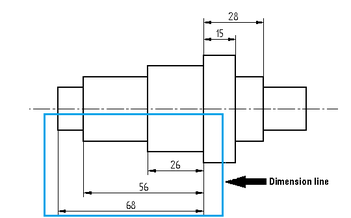
Engineering design glossary of terms Design terms. It indicates direction and extent of a dimension.
Draw The Following Lines Used In Projection I Extension Line Ii Leader Line Iii Construction Line न म नल ख त ल इन क ख च Solutions Ed Question Answer Collection
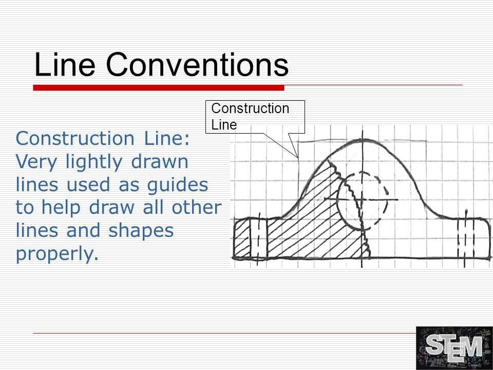
Construction lines are the guiding lines that you draw to help you to draw main lines.

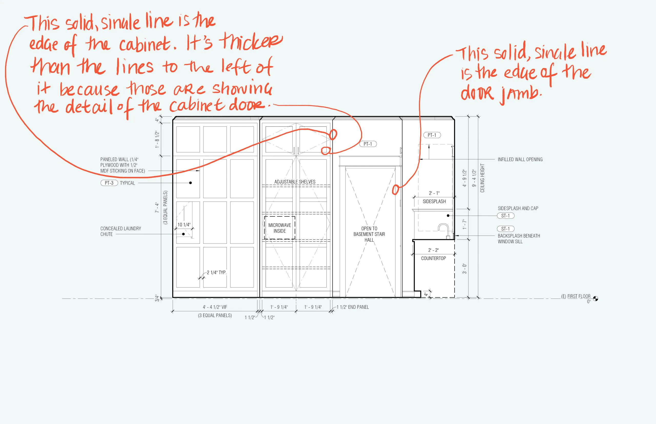
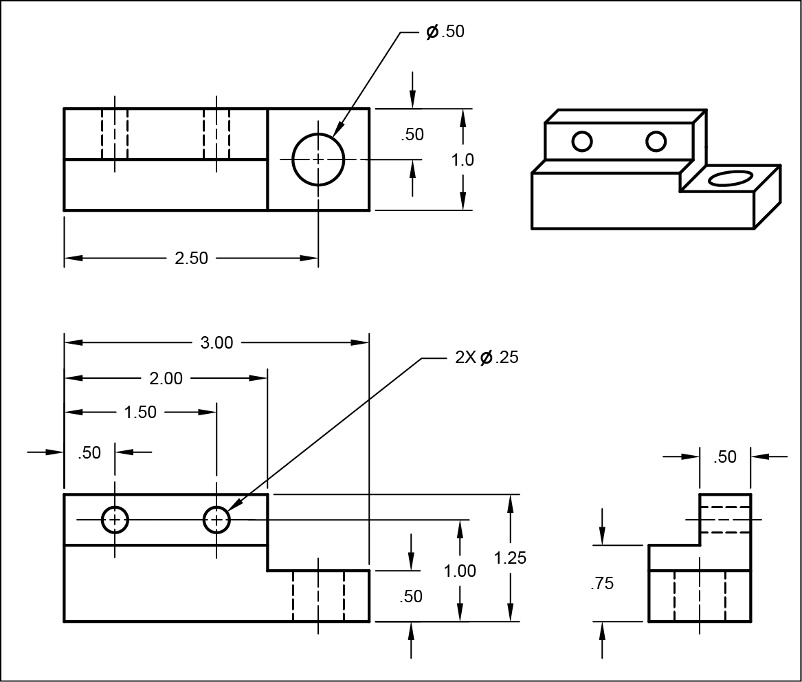
. If you are talking about engineering drawing AutoCAD etc. Engineering drawings also known as mechanical drawings manufacturing blueprints drawings etc are technical drawings that show the shape structure dimensions. Center lines in an engineering drawing show the center of a round or cylindrical shape.
Long dashes are used to begin. Thin lines that serve as guides while sketching or drawing. We also know it as an X-line command in auto.
Drawings are available in various formats including PDF Acrobat DGN MicroStation Design File DWG and DXF AutoCAD. If you are talking about engineering drawing AutoCAD etc. In machine sketches and drawings in which fractions and decimals are used for dimensions the dimension line is.
If the MCC is unimportant ie Ip 10 per ASCE 7 and being installed as part of a new- or existing-building project in which the seismic design of the. Has a short shoulder 3-6mm at one end that begins at the center of the vertical height of the text and a standard dimension arrowhead at the other. Construction lines are the guiding lines that you draw to help you to draw main lines.
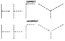
They do not form the part of the. To draw a construction line click on the Place construction line tool and start drawing the first line by clicking anywhere in the active drawing plane then move the mouse. The line is drawn using a thin line with alternating long and short dashes.
A common use is to specify the geometry necessary for the construction of a. A construction drawing set is required on the construction site to carry out any building project. See the state links below for available standard drawings.
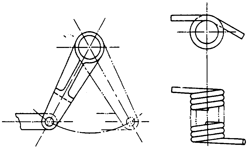
Typically drawn at 45 30 and 60 degrees. Construction line is one of the 2d commands which used as a reference line in our drawing for managing accurate parameters of our drawing. An engineering drawing is a type of technical drawing that is used to convey information about an object.
They do not form the part of the. Definition of construction line. This is done to define the production details such as the materials to be used highly accurate.
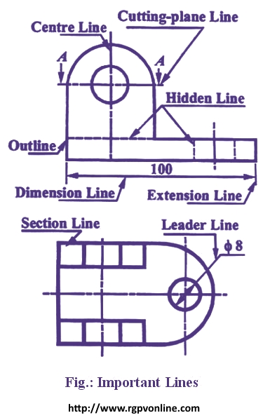
Technical Drawing Alphabet Of Line Schoolworkhelper
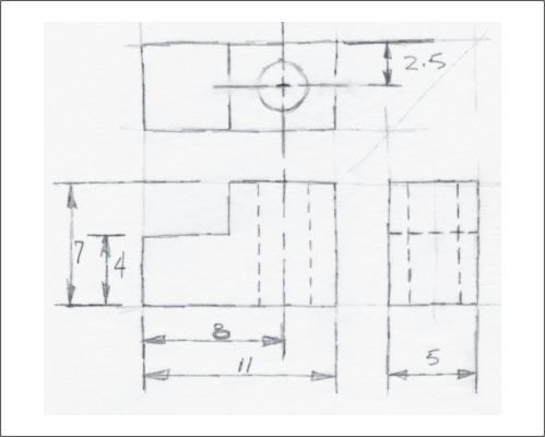
Activity 2a

Tunnel Engineering Drawing A Tunnel Geological Engineering Drawing B Download Scientific Diagram
![]()
Construction Engineering Drawing Tool Icon Vector Image

Divider On Technical Drawing Construction Plan Stock Photo Download Image Now 2015 Architect Architecture Istock
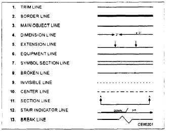
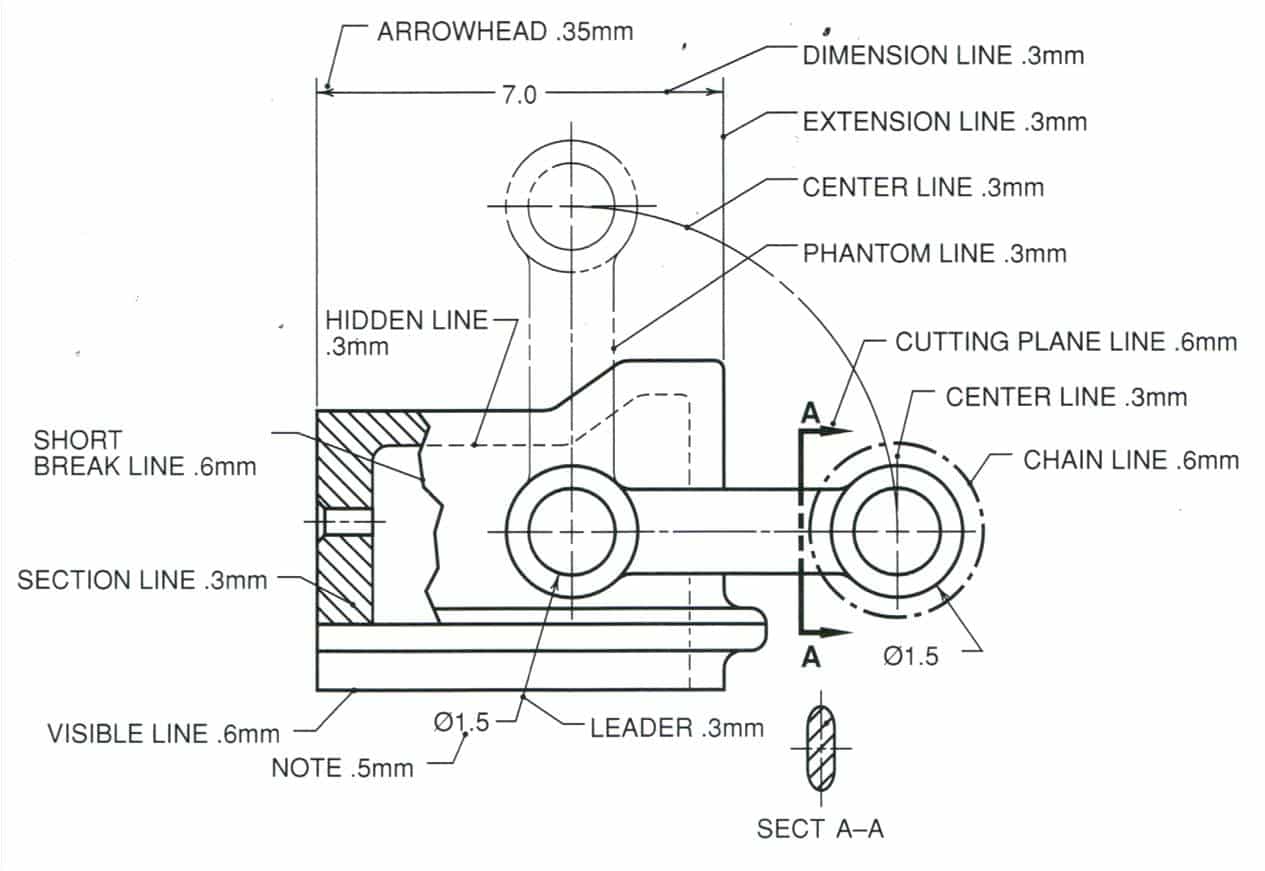
Abbreviations And Symbols

Architect Sketchbook Blueprint Drafting Paper Construction Drawing And Planning Book Grid Paper Notebook 8 5 X 11 Architecture Grid Paper 5x5 Quad Ruled Roebuck Courtney 9798473394078 Amazon Com Books
Types Of Civil Engineering Drawings Engineer Supply Engineersupply
Basic Drafting Skills Line Conventions Ppt Video Online Download
Dimensions And Types Of Dimensioning System How They Used

Projections And Views Engineering Design Mcgill University
What Different Line Types In Architecture Design Drawings Mean Board Vellum

British Standard Line Types Line Art Lesson Types Of Lines Different Types Of Lines

Tunnel Engineering Drawing A Tunnel Geological Engineering Drawing B Download Scientific Diagram
Drawing Linear Features
Engineer On A Disk

Cadforyou Lines And Dimensions
Construction Lines
Line Conventions Manufacturinget Org